As you might know by now, I ride motorcycles. When I do, I like to use my phone as speedometer, GPS and music player. There are plenty of generic handlebar mounts out there, but they all have the same limitations;
- Having the screen constantly on draws a lot of battery, and there is no easy way to charge the phone while riding. Sure, you could connect a power adapter and fiddle with the connector every time you place or remove your phone from the mount, but that is cumbersome – and unsafe if it’s raining.
- Riding in direct sunlight requires setting the screen brightness to 100% to be readable. Aside from the increased power draw issue, no available products I’ve found had a visor that could increase readability on the screen.
- Most handlebar mounts are not made for high speeds. I have previously used one advertised for “bicycles and motorbikes”, but that one came apart while riding over 100km/h on the highway. The phone was only saved by the fact that I had a wired headset plugged in, leaving it hanging until I could safely pull over.
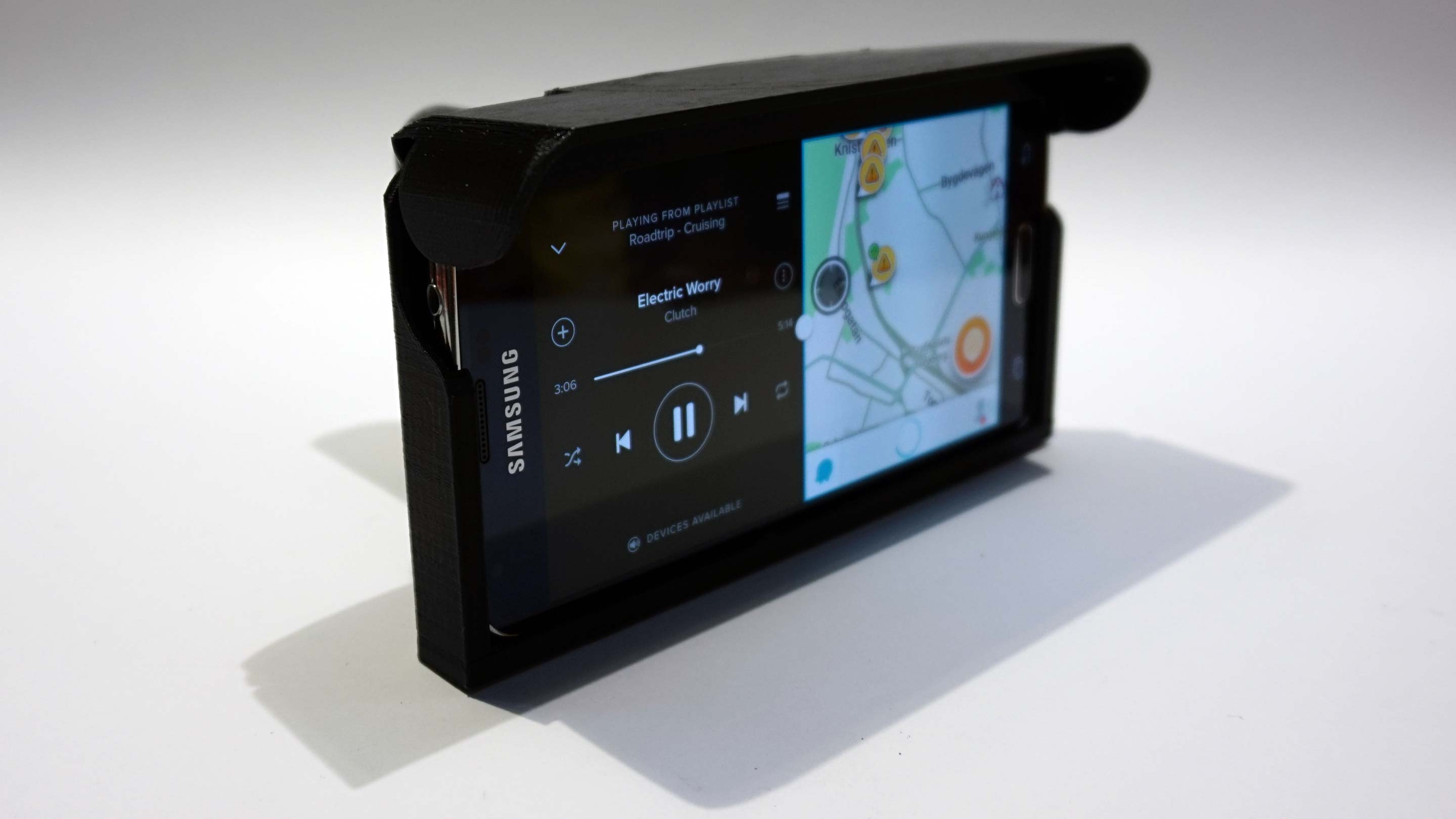
I decided to design and 3D print my own, specifically for my phone; Samsung Galaxy S5, which is itself waterproof unless you open the plastic tab to connect a USB cable to charge it.
After a number of revisions, I had a fully working prototype that included wireless charging. After testing it out, I could refine it further, and I finally had a design I was happy with. It will probably not win any beauty contests, but it’s extremely easy to use and works just as intended. I used the previous revision for more than 10’000 km (from a single print), so it’s been extremely reliable.
I have since made additional improvements and the next version is ready.
Features
- Wireless charging.
- Access to all buttons, including volume. Power button requires you to flip up the visor.
- Weatherproof.
- Drain holes (if left outside in rain).
- Auto locking visor.
- Headphone access.
- Recess for camera.
- Robust
How to use
Flip the lid up, slide the phone in, flip the lid down and you are ready to go. Starting the bike will turn on the built-in Qi charger, which will detect if the phone is in place. If it is, the charger will engage and power the phone wirelessly using resonant inductive coupling. This allows you to have the screen on at all time and still arrive to your destination with a fully charged battery.
Material
I used PLA filament for my prints. I considered ABS, which would at first glance appear to be a better choice, were it not for it’s high sensitive to UV radiation (sunlight). PLA is on the other hand more sensitive to heat, but the temperatures in Sweden rarely go high enough to compromise the structural integrity of pieces of this size. New materials come out all the time, and I’m sure there are better options out there by now, but PLA has worked for me.
Stainless steel mounting
Mounting the holder on the handlebar requires 4 x stainless M6 40mm bolts with Allen/Hex socket heads, along with matching locking nuts. One extra bolt and nut of the same size is used as hinge for the self-locking visor.
If you can get it, use non-magnetic stainless steel – test by holding a magnet to it and see if it sticks. This is to avoid causing interference in the induction-based wireless charging, which can also cause magnetic metal in close proximity to get warm. The charger does have a shielding plate, and even without it the distance to the bolts should be big enough, but better safe than sorry.
Note: Even when specified as non-magnetic stainless steel, bolts and nuts can still have a weak reaction to a magnet. This should be just fine).
Electronics
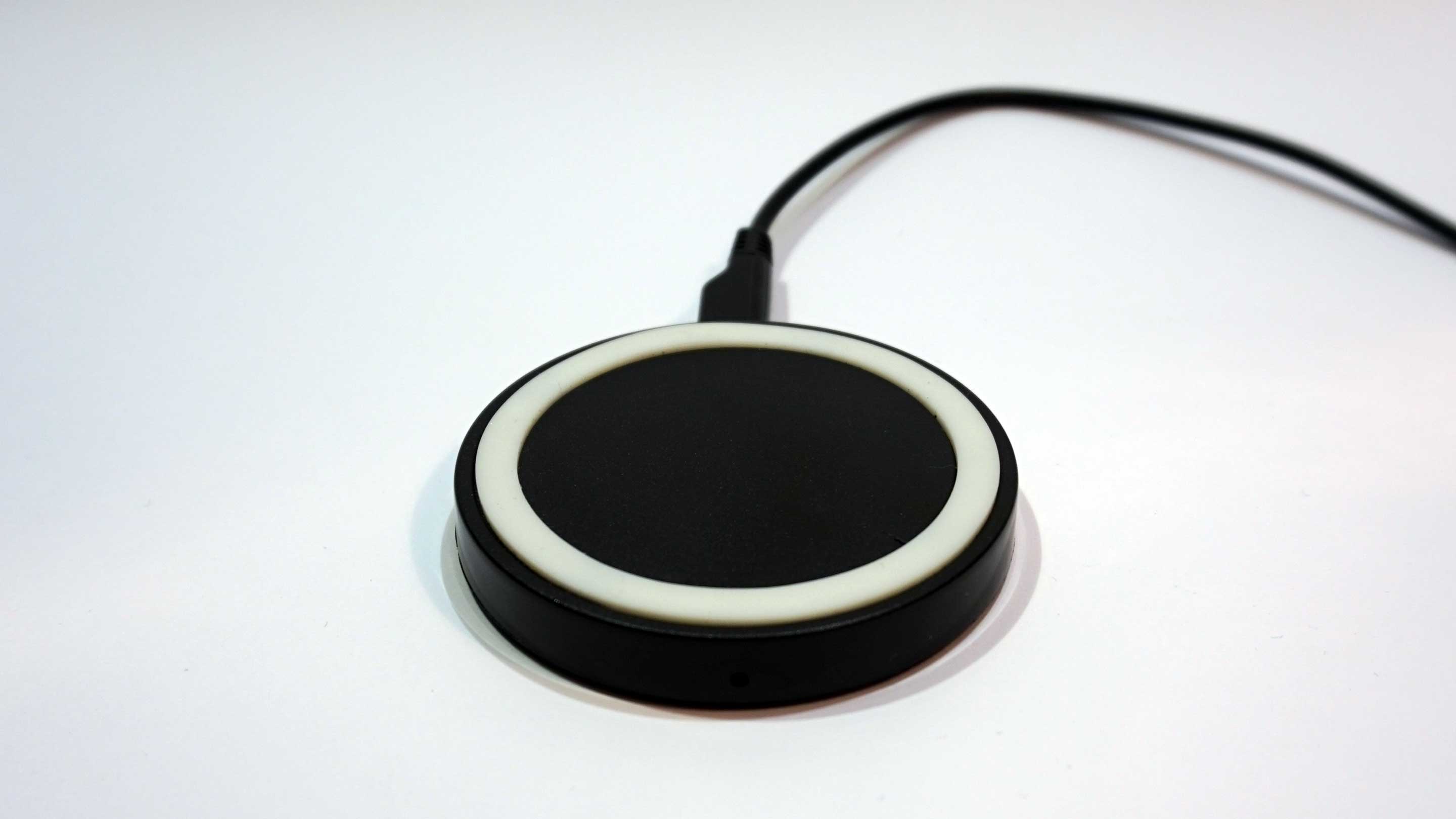
A cheap Qi charger or DIY Qi kit is placed in the compartment directly behind the phone, which will transfer the power from the charger to the Qi receiver pad in the phone. Both the charger and receiver pad can be found on eBay for less than 3€ each, including shipping.
These chargers/kits usually have Micro USB sockets for power input. The power socket is placed downward, at an angle that makes it impossible for rain and splashes to get to it. The charger is then fastened and waterproofed using hot glue or silicon sealant. To power the Qi charger, you have a few options:
A. Use a portable USB battery pack. There are a plethora of options out there in different shape and size. If you don’t want to make modifications on your motorcycle, or want to use this mount on a bicycle, this is your best option.
B. Power it directly from the motorcycle. To do this, you need a 12V to USB (or Micro USB) adapter, you can find cheap waterproof variants on eBay.
Many bikes already have a relayed auxiliary 12V jack inside the headlight housing, this would be the easiest option. If not available, using a relay to only provide power when the ignition is turned on is highly recommended. Though the power draw from the Qi charger itself is minimal when no phone is detected, some power adapters can drain the battery if left connected with the bike not running for a couple of days. A simple switch can be used to prevent this, but you always run the risk of forgetting to turn it off. Using a relay completely eliminates that risk.
This is free
If you want to print one yourself, I’ve made the 3D model freely available on http://www.thingiverse.com/thing:911206
Shopping list
If you don’t already have it, a Qi receiver is needed. This is placed inside your phone between the battery and the back cover. It usually have 2 or 3 pins, depending on model. Additionally, you will need:


Assembly instructions
- Print all parts. Recommended layer height is 0.1mm if you want it smooth. I went with 75% infill to be on the safe side.
- Sand, polish, prime, paint, acetone treat or anything you like (optional). The print shown in photos here did not get any post treatment except for removing supports. This will show you the raw look pretty much straight out of the printer.
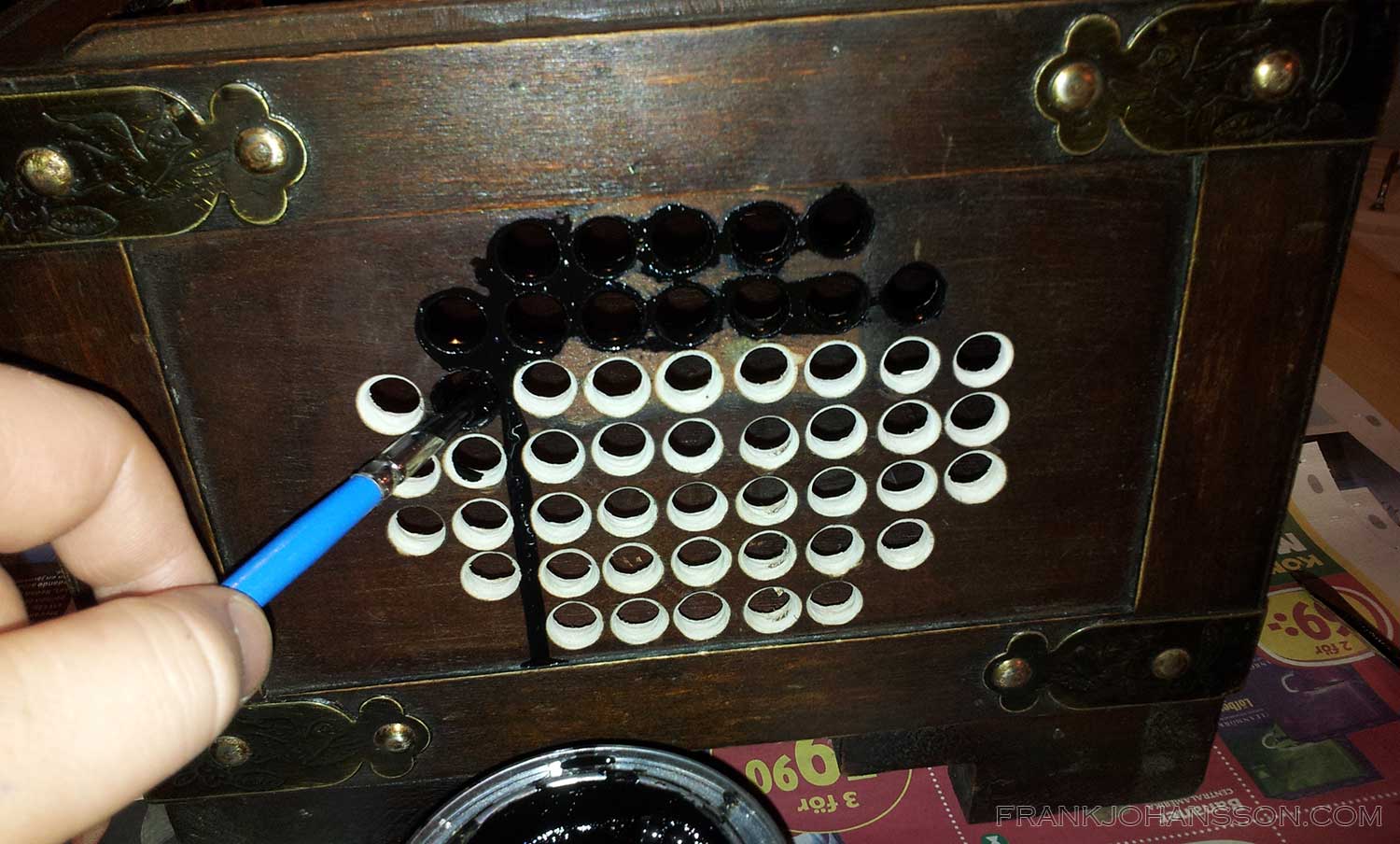
- Test the Qi charger – if you have still not installed the Qi receiver in your phone, see step 8 for an example. Mine shows a faint red light when power is on but no phone is detected, and a bright blue light when a phone is detected and charging. If a phone is detected but has a bad connection (coils in charger and receiver doesn’t line up), it will blink. As you can see, the lower/right side of the phone has a better connection than the upper/left:
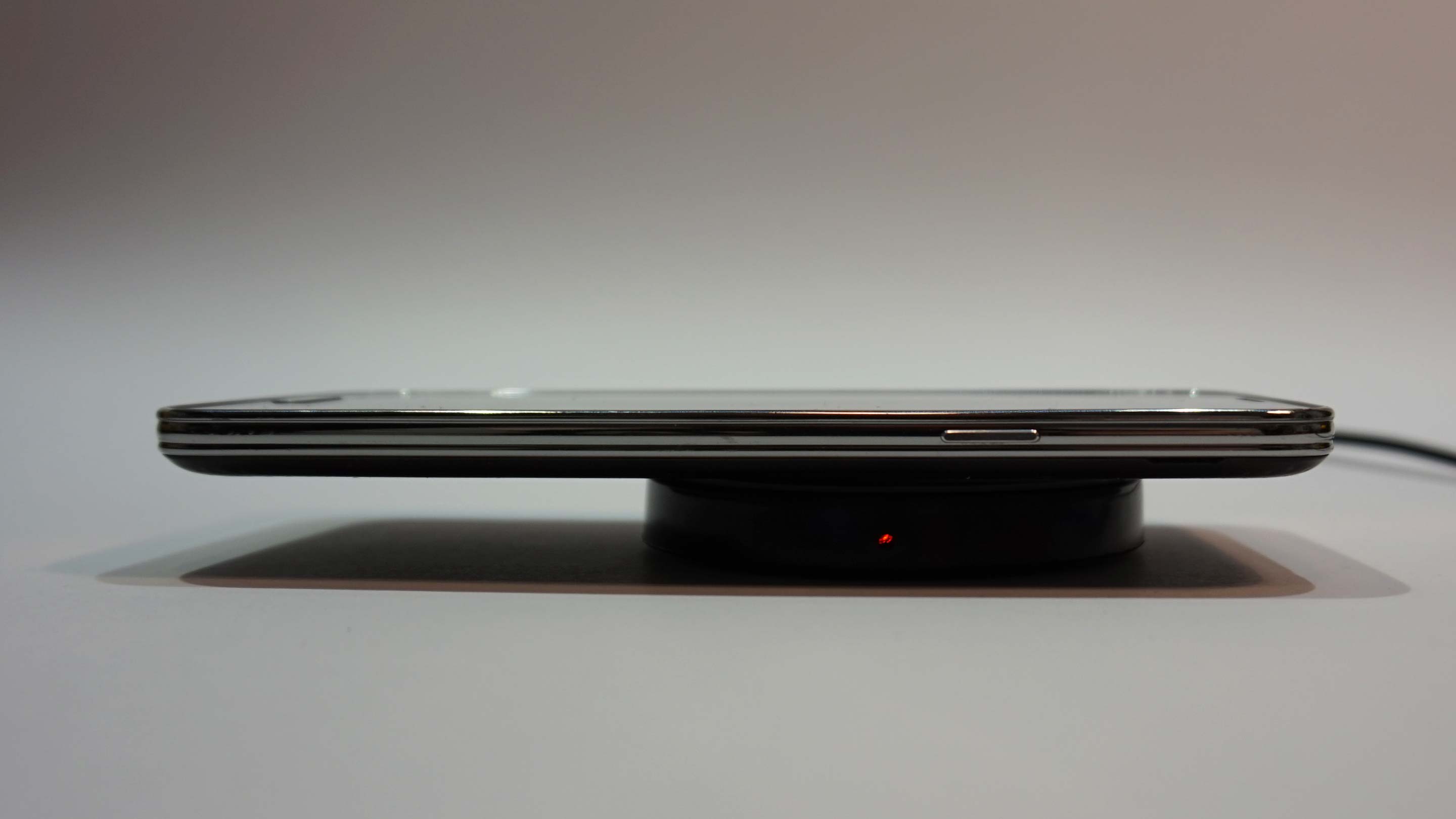
Red light. No receiver detected. 
Blue light. Receiver detected., charging phone - Place the charger in the cavity of the printed mount (body) with the port down. Plug it in and insert your phone. If it charges keeps and doesn’t lose the connection every 10 seconds or so, you can just glue the charger in place and skip ahead to step 16. If not, we need to line up the coils in the charger and receiver.
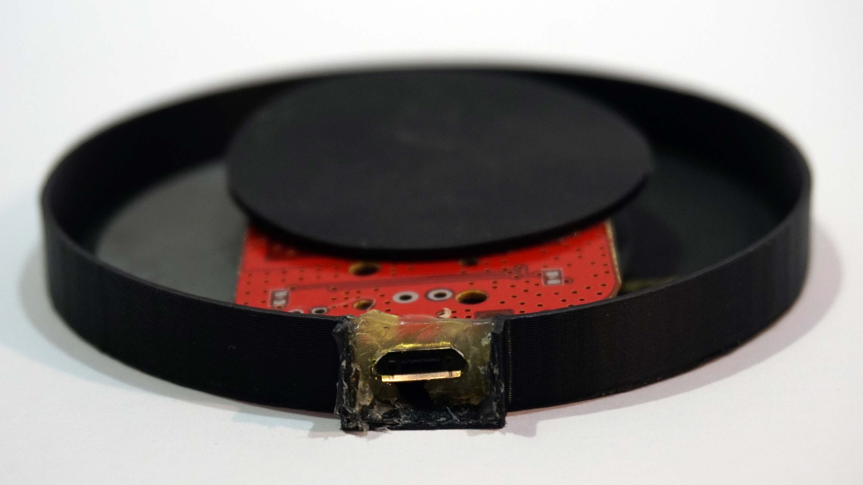
- Unplug the charger and pry it open:

Look Ma’, no hands! - Unscrew any tiny screws that holds the PCB to the case:

The ancient art of balancing precision screwdrivers - Remove the innards of the charger and turn it over. This one has a cracked shield, but should still work:

It’s not all it’s cracked up to be - Next, time to have a look at the Qi receiver. Remove your phone’s rear cover and determine where in the Qi receiver pad the coil is. If not clearly marked out, you can usually feel it by pressing down on it. Here I have marked it out with a colored pen to demonstrate the next step:

No need to be fancy, this will be covered up - Now we need Line up the the printed charger cover to the center of the phone (hint: It’s at 71mm), with the opening of the cover facing towards you. Make a vertical line on the inside of the cover along the center of the receiver coil:

Rule number one - Line up the printed charger cover to the top (from your POV) of the phone. Make a horizontal line on the inside of the cover along the center of the receiver coil. After this you can put the cover back on your phone.

Rule number two: Do not talk about ruler club Read ahead a few steps, the following should be done in a fairly quick order:
- Add a few dabs of hot glue or epoxy glue to the charger coil:

Hot dang! - Turn the coil over and place it as close to the cross marking on the cover as possible while still being able to reach the Micro USB port through the opening of the case. Attach a cable to make it easier to see if the port can be reached and is straight:

Work fast - Hold the PCB straight and apply hot glue or epoxy generously to the port with the cable still attached. (Tip: If you don’t want to clean up glue from your fancy cable, use a sacrificial or already broken cable. It only needs to be attached in this step to prevent glue from entering the port.)
Keep adding glue until it it reaches the brim of the cover, while holding the PCB steady until the glue begins to solidify. The glue will both keep the PCB in place and keep moisture out.
Don’t be afraid of using too much glue. It is non-conductive, will not short anything out and will not damage the PCB. - After a minute or two, before the glue (or epoxy) is fully hardened, unplug the cable while holding the PCB secure. We only want the cable loose, not all the glue.

Will be cleaned up - Let it solidify completely, then trim the excess glue along the port edge. The entrance to the cover should now be completely sealed, while allowing a Micro USB cable to be connected.
It’s functional - Time for the next chapter. We will now attach the charger/cover to the main body of the mount, then seal the edges.
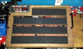
Start by masking the body (cavity side) with masking tape, then trimming the edges with a scalpel or craft knife, This will help us get a nice sharp edge for the sealant. - Place the charger/cover in the cavity with the port facing the bottom hole of the body.
- Apply a sealant as hot glue, epoxy glue or silicon along the edges of the cover. If you don’t want it all over the cover, you can place something round in the middle, such as the bottom of the original Qi charger case:

Bottom of original Qi charge case is used to create a nice edge for the hot glue - Before hardening completely, remove the center object (if used):

Scalpel used to make sharp edge - Trim sealant with something sharp:

Excess sealant trimmed with scalpel. Qi case bottom used as center sealant blocker removed. - Remove masking tape:

All cleaned up - Place phone in the mount to make sure the sealant is not protruding so much as to block it:

It fits! - Place two nuts in the upper holes as in the photo. Nylon lock (if used) should point up:

Lock it up - Place the visor so that if blocks the nuts. Fasten it with a bolt and nut:

Holding the nut with pliers might help while tightening the bolt. - You should now have something that resembles an angry pig:

Angry pigs are angry - Place the phone in the mount and make sure that you can close the visor:

Almost done! - Connect a Micro USB cable to a charger and verify that the phone is charging:

It’s alive! - Insert the remaining two nuts. You can now attach it to your handlebar using the clamps and bolts:

Everything in place - Connect the 12V to Micro USB cable. You’re all done!
Enjoy your new mount! Now you never have to worry about getting lost or your phone running out of battery while riding again. Just remember to keep your eyes on the road!