The volume control on my guitar amp does not behave as I want it to.
Today it is like this:
Amp volume at 0 = (silence)
Amp volume at 1 = LOUD
Amp volume at 2-10 = LOUDER
This is a problem when using a distortion pedal without a dedicated volume control, as our very easily disturbed neighbors starts banging the wall at volume 1, and I sometimes want to play without headphones.
For the distortion to really kick in I can’t lower the volume knob(s) on my guitar too much either, so I had to introduce an additional volume control to take effect after the pedal.
In short, I needed to go from here:
[Amp]<--[Pedal]<--[Guitar]
to here:

[Amp]<--[Volume]<--[Pedal]<--[Guitar]
So I made a small volume controler using a 500k potentiometer and two 1/4″ jacks. I didn’t have a good enclosure at hand so I simply used an old plastic medicine jar.
About two months ago I bought an electric guitar after a 17-18 year long hiatus. A cheap Les Paul copy that looks good but plays bad. 😉 I also bought a few effect pedals such as Overdrive, Distortion and Echo/Delay. And then a few more. I realized that I needed a pedalboard to avoid having to patch in everything and getting wires all across the floor whenever I wanted to play. I was looking at a number of the pre-made solutions and also a few custom ones before deciding to build one myself. Wanting to add some additional functions and a semi-retro style, I decided to go with wood as my material of choice. After measuring, sketching, drawing and calculating about two weeks I had a finished design. I bought two pine planks and began by drawing up lines for everything that were to be cut and drilled. I wanted an empty place on the right side where I could add additional pedals such as Wah, or as in the pictures below, a multi-effect pedal. After producing the rough pieces, I began sanding everything by hand. Since this is not going to be displayed on a pedestal in an art museum, I only went with 120 grain paper. The top parts were first glued, then drilled and screwed for additional stability. After a single layer of wood stain, I assembled the pieces using a piano hinge for opening the lid and a pair of chest clasps for fastening the lid when closed. Wanting something to carry the pedalboard with, I opted for IKEA ULVSBO drawer handles. While at IKEA, I also picked up the laptop support BRÄDA, which after cutting out a piece from a lower corner and flipping upside down was a perfect fit for the dashboard. Filing the corners and sanding it in a single direction made it look a bit like ebony. Adding all jacks, switches and panels, next up was the soldering. No biggie. Aside from power, I wanted 4 jacks on the pedalboard:
Guitar in. Also used if you want to add additional pedals first in the pedal chain.
Aux in. Will be sent directly to the output(s) so that you can attach your phone or audio player for jamming without it being affected by the pedals. I might add a separate booster/volume control to this later.
Amp out. Also used if you want to add additional pedals last in the pedal chain.
Headphones out. I might add a separate booster/volume control to this later.
The control panel has the following functions
Main power. Powers the whole pedalboard on/off
AC/DC. There is a 2x9v battery compartment (connected in parallel) under the lid for powering the pedals with batteries instead of using an AC/DC adapter. This switch allows you to change power source on the fly.
Pedals/Bypass. Allows you to send the Guitar in signal directly to the outputs, bypassing all pedals.
Voltmeter. Very useful when running on DC power to see how much is left.
All power cables are detachable and reroutable. This gives you the option to power only one or a few pedals with battery power and the remaining pedals with the transformer. This includes the main power switch, voltmeter and LED strips. If running everything on batteries, it eats batteries fast – especially the Korg RP50 multi-effect – but it works! After adding some industrial-strength Velcro, it was only a matter of arranging the pedals how I wanted them, patching the audio signal and routing the power cables. I also added TDK ferrite cores around all patch/power cables to minimize electrical interference. Being only the second wood-based project I’ve done since I was 15, I’m quite happy with the results. What would you have done different? I am already thinking about version 2. 🙂
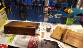
Drawing of pedalboard before cutting.
After cutting and rough sanding, pieces are glued. Handle holes are used to temporarily drill top and bottom pieces to make sure pieces are glued at correct angles.
After more sanding, stain is applied.
Top screws are remaining for added stability of lid.
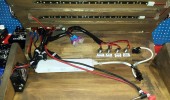
Jacks are added and soldered, power switches are connected.
Velcro is applied, power is tested
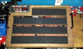
Pedals are added and attached. Tested in light…
…and in darkness.
Left side, the clasps is holding the lid closed.
Right side. A hole allows you to pull power and patch cables to the inside.
Rear view. The end of the signal chain is patched to the multi-effect pedal on the side.
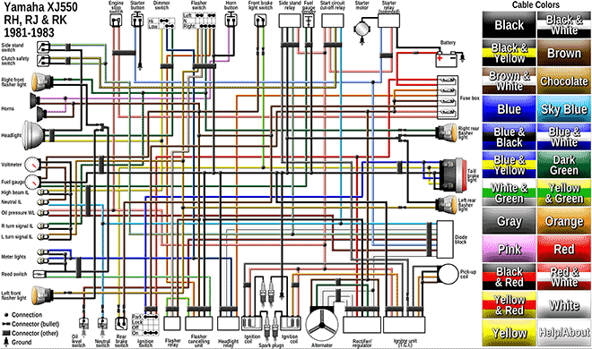
About a year ago, I was doing a little project for one of my motorcycles. I noticed it was hard to come across a good, accurate electrical diagram for Yamaha XJ 550. So I decided to make one myself. But one magnitudes better. And interactive.