Our home server/HTPC broke down after close to 6 years, and it was time to replace it. Being me, I didn’t want to just buy an off-the shelf machine – where’s the charm in that?
This one is a little different than my previous builds. I didn’t modify an existing enclosures this time, but instead created one completely from scratch. 3D modeled and 3D printed based on nothing more than my own ideas and my own measurements.
I do like reusing and repurposing existing things, and I try to not get stuck in a throw-away mentality. This new case is however entirely made from renewable or recycled materials. The main body is printed using biodegradable PLA plastic (made from corn starch or cane sugar). The only other parts of the case consist of a power switch and an LED, both taken from the failing computer it was meant to replace.
I had an idea of a completely smooth case without any visible corners, with a single air inlet on the top connected to the CPU fan. A number of smaller air outlets near the bottom would force the airflow to spread out around the motherboard and the rest of the components. The shape would initially resemble a simplified cloud, but that quickly changed.
I was impressed with the layout, performance and tweakability of the Asus H81T Mini-ITX motherboard that I used for the 1-Up NES case mod, and decided to use another one for the new case. Most important was the fact that the H81 has a rear power jack that fits standard laptop power bricks, and I could pick up a used one from Dell on eBay that worked right away, no modifications needed.
I used a modeling tool that I already knew; Tinkercad – a free, browser-based online CAD tool from AutoDesk. It has limited functionality and performance, and I’m planning on learning a “real” CAD program soon (Fusion 360?), but I was eager to get started right away. After a number of versions and revisions, I had a rough printed version (5) up and running 24/7 for about a month. After a lot of checks, changes and tweaks, I finally printed the final version (8) on my heavily modified RigidBot 3D printer. By now the initial project name Fluffy had changed to Frosty, and the design would now look more like snow than a cloud. I made a snowflake design for the air inlet, which also serves as a fan guard.
After sanding I applied a few layers of acrylic clear coating to get more of a snow crust look. PLA is notoriously hard to sand as it melts and clumps up if you go too fast due to the friction. I only went up to 240 grit, which is why the surface isn’t perfect. If this was a job for someone else I would go to at least 800 grit, but as it will only be used at home this is good enough.
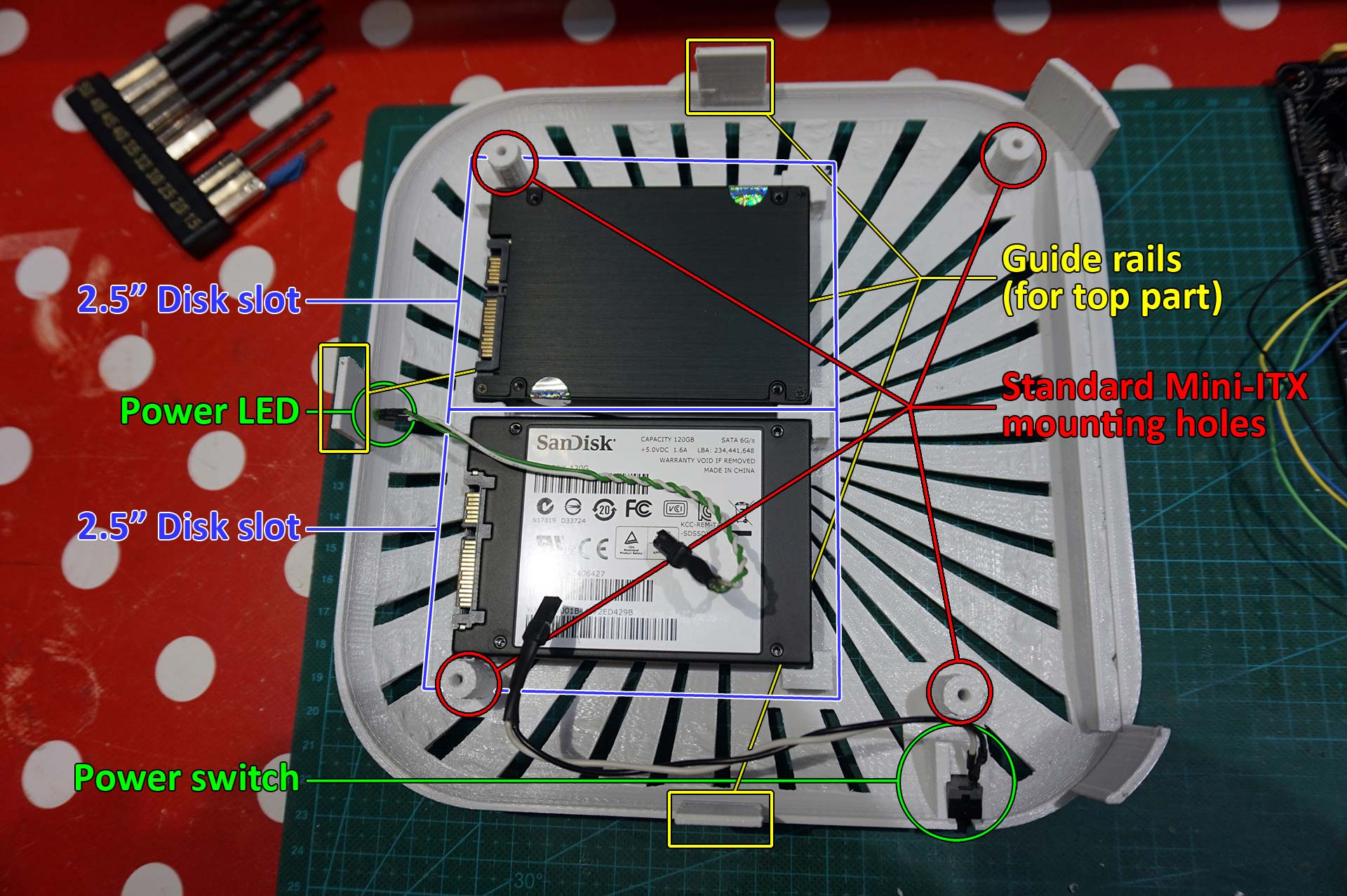
Bottom and top parts after sanding and clear coatingInsides before assembly
When assembling the computer, pretty much everything fit perfectly. I only had to drill the hole for the LED a tiny bin larger and use a scalpel to shave off about 0.2mm for the power switch.
Unless you have your ear right next to the computer, you can’t hear it running. Since I use an SSD, the only moving part in the computer is the CPU fan, and Intel did a fantastic job with making it whisper quiet – at least when enabling the Q-Fan control in the UEFI bios.
With the CPU on full load on all cores at 3.2Ghz, the computer is still almost dead silent and the CPU temperature is usually around 30°C.
All in all, I’m happy with the results. I’ve learned a lot and had fun doing so.
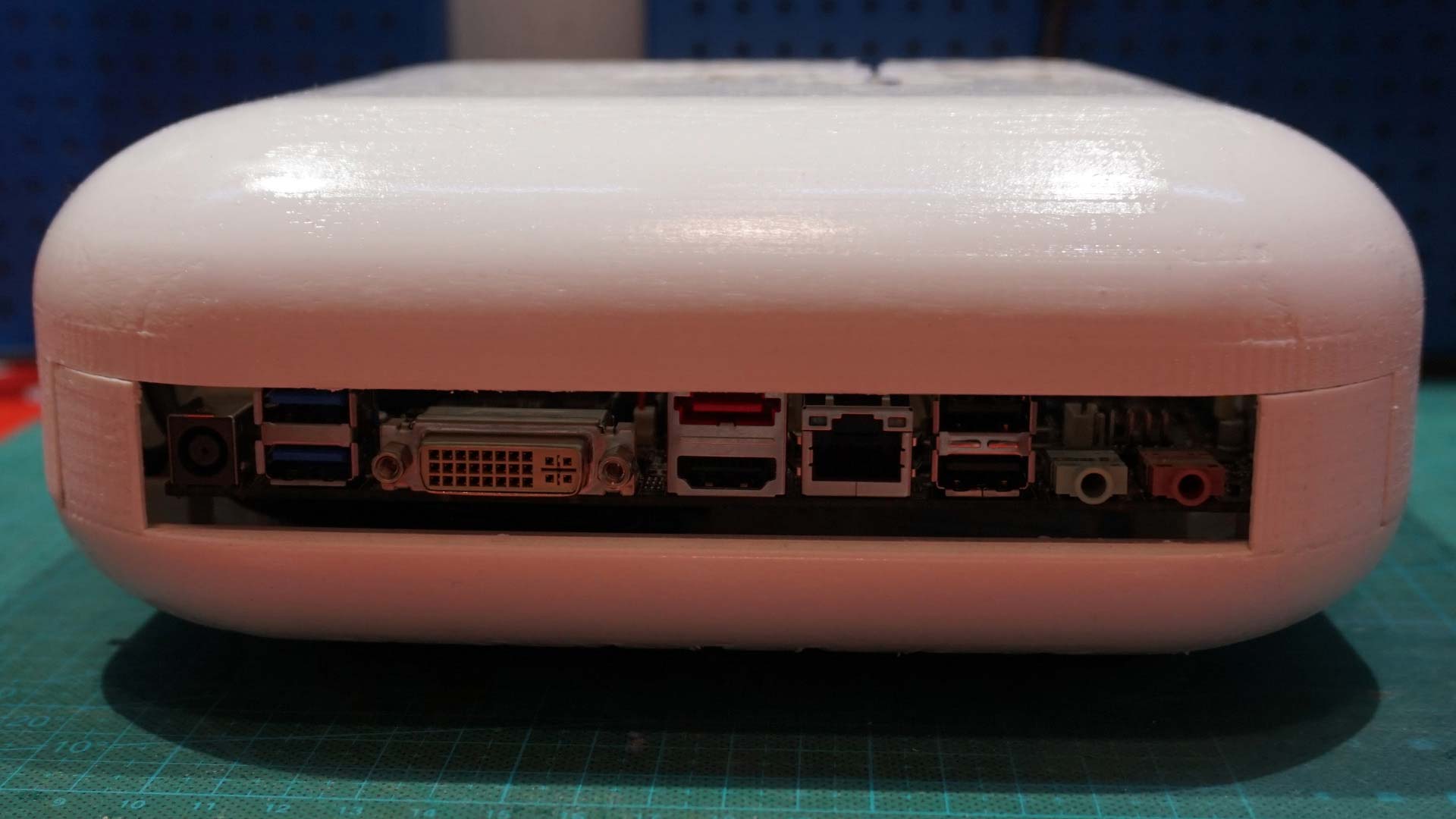
Outline of case functionalityPower LED insertedPower switch insertedEmpty case, seen from rearFully assembled case, seen from rearEverything in place except top coverEverything in place including top coverAt it’s current home, next to external HDD. Previous computer occupied entire shelf, hence the extra space.
Ok, this was a while ago, but it was a fun project.
My wife (before we got married) needed a new computer. I had a non-working Nintendo Entertainment System in a box. As she is a big Nintendo fan, I decided to build her a special system.
I had three goals with this build, all of which were fulfilled:
A. It had to be powerful. Based on an Asus H81T board using a 3.5GHz Intel Core i3 CPU and a Crucial SSD, it’s fast enough for any games, videos and other tasks given so far. It boots in about 10 seconds.
B. It had to be quiet. The Intel stock CPU cooler is exceptionally silent, and you have to be very close to the case in order to hear it. This is the only moving part in the system.
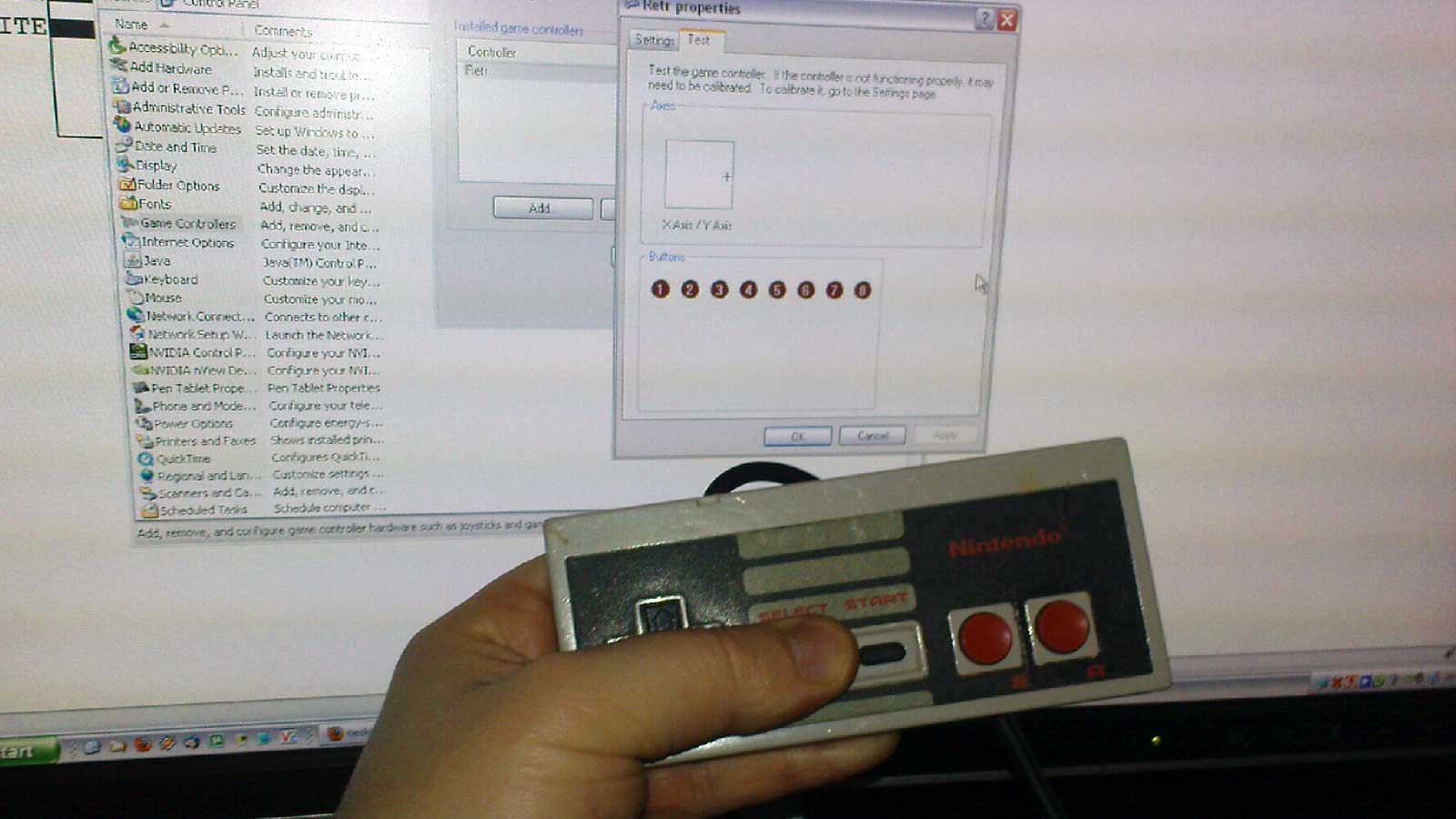
C. The original controllers had to work. The end result is fantastic, if you are playing original NES games using an emulator, the controllers have the exact same feel as on an original system. Zero lag or other negative effects are experienced.
So, how to do it?
Step 1: Gut it.
Original NES case opened up. The procedure to unscrew and remove everything was very simple.
I wanted to reuse the original switches and joypad connectors, so I left them intact for the time being.
Step 2: Mod the case bottom.
In order to fit the motherboard with a mounted CPU and fan inside the case, every extra millimeter had to go. Motherboard mounting sockets were hot glued in place. The taped parts were later removed as well, and a thin stabilizing bottom plate was installed.
Step 3: Mod the buttons.
The original power/reset button platform turned out to be too deep and would short the motherboard if left as is. So I came up with my own version, using flat key switches on a peg board, covered by heat shrink tubing after soldering.
Using a leftover IKEA bracket to hold the new button platform in place, I could shorten the original button shafts and reuse the original springs, giving about the same tactile feedback as the original buttons.
With the new power/reset switches, I could fit the motherboard with about 2mm to spare. The original power LED was replaced with one from a previous PC case.
Step 4: Mod the controllers.
To retain original controller compatibility, I bought two controller chips to convert the original controller signals to standard USB.
Since I did not want anything extra sticking out the back of the case, I converted the standard USB connectors to onboard headers to fit directly on the motherboard. This also allowed me to minimize the length of the wires.
Carefully testing that everything worked as expected on another computer before cleaning up and isolating the controller mod. No special drivers were needed.
Step 5: Fit the hardware.
Using JB Weld to fasten a small furniture angle to a disk bracket from an old MP3 player, I could attach an SSD to one of the original case’s screw sockets in the exactly right position. A rubber strip was added to the top side in order to stabilize it and fit snugly to the top of the case.
Everything in place, including a green LED strip around the case edges. I was able to find a 5V version (they are usually 12V), so I could tap the power directly from an onboard USB header without any power conversion needed.
Step 6: Mod the case top.
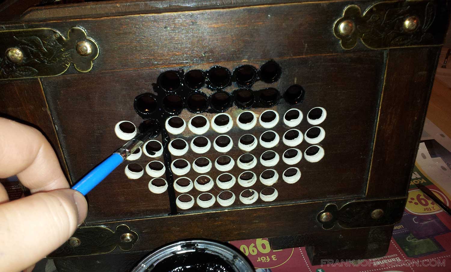
As a computer needs cooling/airflow, I wanted to do it in style. Just drilling a grid or cutting open the sides were not an option. I put on masking tape, outlined a grid and drew up the classic mushroom from the Super Mario games.
After carefully drilling the holes, the shape became clearer.
After cleaning up and filing all the edges, the system was finally ready to be assembled and tested. All OK! OS installation in progress.
All done!
LEDs connected and system up and running! Power LED not yet connected in the picture.
She was very happy with the birthday present, and it has been running smoothly for over a year now. 🙂
The volume control on my guitar amp does not behave as I want it to.
Today it is like this:
Amp volume at 0 = (silence)
Amp volume at 1 = LOUD
Amp volume at 2-10 = LOUDER
This is a problem when using a distortion pedal without a dedicated volume control, as our very easily disturbed neighbors starts banging the wall at volume 1, and I sometimes want to play without headphones.
For the distortion to really kick in I can’t lower the volume knob(s) on my guitar too much either, so I had to introduce an additional volume control to take effect after the pedal.
In short, I needed to go from here:
[Amp]<--[Pedal]<--[Guitar]
to here:

[Amp]<--[Volume]<--[Pedal]<--[Guitar]
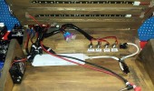
So I made a small volume controler using a 500k potentiometer and two 1/4″ jacks. I didn’t have a good enclosure at hand so I simply used an old plastic medicine jar.
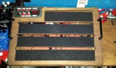
About two months ago I bought an electric guitar after a 17-18 year long hiatus. A cheap Les Paul copy that looks good but plays bad. 😉 I also bought a few effect pedals such as Overdrive, Distortion and Echo/Delay. And then a few more. I realized that I needed a pedalboard to avoid having to patch in everything and getting wires all across the floor whenever I wanted to play. I was looking at a number of the pre-made solutions and also a few custom ones before deciding to build one myself. Wanting to add some additional functions and a semi-retro style, I decided to go with wood as my material of choice. After measuring, sketching, drawing and calculating about two weeks I had a finished design. I bought two pine planks and began by drawing up lines for everything that were to be cut and drilled. I wanted an empty place on the right side where I could add additional pedals such as Wah, or as in the pictures below, a multi-effect pedal. After producing the rough pieces, I began sanding everything by hand. Since this is not going to be displayed on a pedestal in an art museum, I only went with 120 grain paper. The top parts were first glued, then drilled and screwed for additional stability. After a single layer of wood stain, I assembled the pieces using a piano hinge for opening the lid and a pair of chest clasps for fastening the lid when closed. Wanting something to carry the pedalboard with, I opted for IKEA ULVSBO drawer handles. While at IKEA, I also picked up the laptop support BRÄDA, which after cutting out a piece from a lower corner and flipping upside down was a perfect fit for the dashboard. Filing the corners and sanding it in a single direction made it look a bit like ebony. Adding all jacks, switches and panels, next up was the soldering. No biggie. Aside from power, I wanted 4 jacks on the pedalboard:
Guitar in. Also used if you want to add additional pedals first in the pedal chain.
Aux in. Will be sent directly to the output(s) so that you can attach your phone or audio player for jamming without it being affected by the pedals. I might add a separate booster/volume control to this later.
Amp out. Also used if you want to add additional pedals last in the pedal chain.
Headphones out. I might add a separate booster/volume control to this later.
The control panel has the following functions
Main power. Powers the whole pedalboard on/off
AC/DC. There is a 2x9v battery compartment (connected in parallel) under the lid for powering the pedals with batteries instead of using an AC/DC adapter. This switch allows you to change power source on the fly.
Pedals/Bypass. Allows you to send the Guitar in signal directly to the outputs, bypassing all pedals.
Voltmeter. Very useful when running on DC power to see how much is left.
All power cables are detachable and reroutable. This gives you the option to power only one or a few pedals with battery power and the remaining pedals with the transformer. This includes the main power switch, voltmeter and LED strips. If running everything on batteries, it eats batteries fast – especially the Korg RP50 multi-effect – but it works! After adding some industrial-strength Velcro, it was only a matter of arranging the pedals how I wanted them, patching the audio signal and routing the power cables. I also added TDK ferrite cores around all patch/power cables to minimize electrical interference. Being only the second wood-based project I’ve done since I was 15, I’m quite happy with the results. What would you have done different? I am already thinking about version 2. 🙂
Drawing of pedalboard before cutting.
After cutting and rough sanding, pieces are glued. Handle holes are used to temporarily drill top and bottom pieces to make sure pieces are glued at correct angles.
After more sanding, stain is applied.
Top screws are remaining for added stability of lid.
Jacks are added and soldered, power switches are connected.
Velcro is applied, power is tested
Pedals are added and attached. Tested in light…
…and in darkness.
Left side, the clasps is holding the lid closed.
Right side. A hole allows you to pull power and patch cables to the inside.
Rear view. The end of the signal chain is patched to the multi-effect pedal on the side.
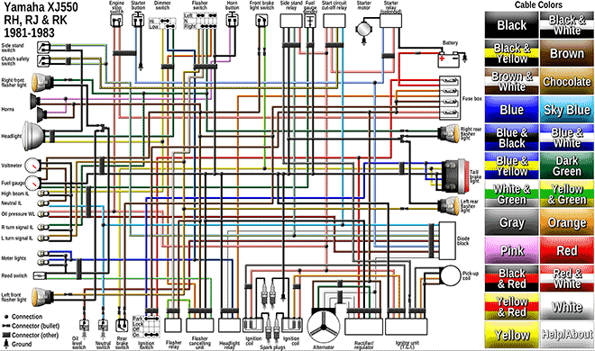
About a year ago, I was doing a little project for one of my motorcycles. I noticed it was hard to come across a good, accurate electrical diagram for Yamaha XJ 550. So I decided to make one myself. But one magnitudes better. And interactive.
The Chest Case mod project has been moving forward! If all goes as planned (which it rarely does), the final assembly will be tomorrow!
First off, I made two errors while making the design:
I forgot to take the cables into account
I forgot to take the cables into account
To start, the HDD/SSD cage will have to be moved from behind the PSU. Since the PSU is modular, meaning you can attach and remove the power cables, the removable cables are taking slightly more vertical space due to the connectors to the PSU. This means I’m about 1 cm short of fitting the drive cage in the planned space. I will therefore relocate it higher up, elevated partly inside the chest lid. It will still not be visible when the lid is closed, but will be the first thing you see if you open it.
Secondly, I did not study the physical component design of the motherboard before starting this project. All the motherboards I have ever used in the past when building computers have had their HDD (ATA/SATA) sockets flat on the top of the motherboard. This one has it on the side, on the opposite side of the rear panel where the USB, audio etc. ports are. That means that the SATA cables won’t fit unless I open a hole in the front of the chest for this very purpose. All angled SATA connectors are angled the wrong way, pointing down to the bottom of the chest. Or so I thought, after trying the three different kinds I had at home. After some scouting I did however find SATA cables with inverted angles, meaning the actual cable would point straight up. The space for the connector was still too tight though, only leaving a few millimeters to the edge, where it would be impossible to fit any connectors at all. However, carefully grinding down part of the front board of the chest from the inside proved to give just enough space to fit the cables. I did have to be very careful when grinding though, as the front board is only about 4 mm thick. When done, the board was only about 1 mm thick in the area where the SATA ports are.
Other than that, I have drilled, filed, grinded, polished and cut the case to have all the openings it needs to have, from air vents for the fans to a large opening for the PSU and motherboard rear panel.
Today I did some last revisions to fit the video card that was slightly to high when fitting it, and finished off with staining all the cuts and holes (“Dark Oak” dye), and also applying it to the surrounding chest panels for it to blend in better.
Tomorrow I will pick up the inverted SATA cables and a proper version of Windows 7, and I’m hoping to have the entire computer up and running tomorrow or the day after that.
1. Remove the lid
2. Apply masking tape
3. Drill guide holes from the outside
4. Find guide holes and draw outer frame on the inside
5. Measure and draw venting hole grid
6. Drill guide holes
7. Expand and drill larger holes
8. Remove tape
9. Find the positions for the components
10. Measure and draw where the holes are to be cut
11. Cut and saw the holes
12. Repeat steps 5-8 for the other side
13. Thread a piece of plexiglass where the motherboard will be mounted
14. Grind down inside of front board where the SATA ports will be placed
15. From 4 mm to 1 mm thickness
16. Drill an additional hole in the front/bottom for a power button
17. Paint all holes and bare edges with dark oak stain
18. Use a sponge to stain the surrounding boards to get rid of bad stain egdes
19. Use stain on similar areas on the lid as well
20. My assistant hot gluing the power button to an old coat button.
The packages arrived today!
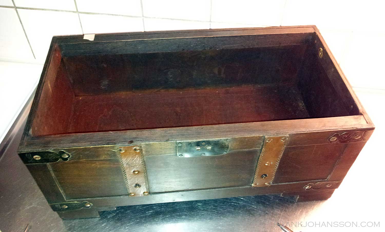
In the image below you can see the components around the chest where I plan to stuff it all soon. In the background is a full size travel chest, so you can see the size difference. This will be my own personal little treasure chest. 😉
Last week I ordered a bunch of components for building a new computer. The main reason is that I want to be able to use triple screens with Eyefinity, and my current setup can’t handle that. I’ve been using dual monitors for about 7 years and never looked back, but I would like some more screen estate, especially when working in Photoshop and the likes, and playing 3D games. Games like Dragon Age (I/II) etc works fine with dual screens, but I find it annoying that all texts etc are split in the middle between two screens. For better vertical resolution, I will use my three 21″ Dell screens with IPS panels with extreme viewing angles and a lot better color depth than “normal” computer screens. And they can pivot, meaning I can place them vertically. The full resolution will be 3150×1680 with an aspect ratio of 15:8, slightly wider than standard 16:9 widescreen. And since my current computer is 5 years old, I thought it was about time to buy a new rig anyway.
The thing I enjoy most about getting a new computer is to build the case. To be able to fit the 3-slot wide, passively cooled graphics card alongside the CPU cooler, I could not go with a 17x17cm Mini-ITX motheboard this time as I have for my last two builds, but had to step up a level to a 24x24cm Micro-ATX instead. The size for the components are perfect for a case that I will build out of a small wooden chest. I will try to make the chest to look as close to the original as possible, not revealing that it actually contains a computer until you get a closer look at the sides and the rear.
Since everything but the CPU is passively cooled, even the PSU, the case will require some airflow as to not overheat. I will go for a silent 12cm fan on each side with adjustable speed that you can turn up if needed while playing heavy games or during a hot summer (Or I can just open the chest lid). The big problem will be to have air vents in the chest without it looking too strange. Right now I’m in the decision process on whether I will cut a 12x12cm hole on each side and place a fan grill above them, or if I will simply cut a lot of smaller holes in the chest around where the fan will be placed on the inside.
Two days ago I downloaded Google SketchUp, a free 3D modeling program, to do a design draft and make sure all components will fit. It was quite easy to learn, and after about a total of 8 hours learning and designing, I’ve come up with this. All done from scratch:
The lid in the model is semi transparent in order to actually see the parts inside the chest. Everything is made with millimeter precision, and I’ve used my slide caliper plenty to measure everything correctly. To be less then modest, I’m quite impressed with the progress I’ve made in this short time. I do have previous 3D modeling experience, but that was back in 1995-96 in Autodesk 3D Studio for DOS. I can tell you this: SketchUp is a lot easier to learn.
The computer components are all top notch, and it’s hard to get better components than these without a major step up in price:
Actually, it was done about two weeks ago, I just hadn’t taken the time to give you the update.
It is now working fine, but I might replace the PSU with a full-sized ATX one due to unacceptable noise levels in the current FSP AC-DC 200W SFX12V PSU. Hiper HPU-4S425 looks promising. The problem is that a full sized ATX won’t fit in the case if located where the current PSU is. I am thinking about placing it above the drive cage which would also giving it better airflow and hopefully lower RPM. The problem is that I would have to build a second floor in the cage, and I’m uncertain how it would affect airflow and temperatures for the drives and motherboard (already actively cooled).
We’ll see.
Wanna see? Have a look:
I temporary placed everything in the first wooden case while waiting for the bakelite version to arrive.
The radio as it were before stripping it.
I started by removing the back.
With the help of my friends Mr. Screwdriver and Mr. Wire Cutter, the innards were soon cleaned out.
The actual radio receiver taken out.
Removing the cover plate. I used a towel underneeth as to not scratch the front.
Due to an extremely tight fit of the motherboard, I had to cut the lower part of the cover.
Some hot glue allowed me to use an original switch as a power button.
Screwing the power switch in place.
Testing that everything really fits. It’s tight, but it works.
From the front with the lower part of the cover gone.
Using a plastic clad wire as the station needle.
Some soldering were required for the LEDs lightening the glass.
Lightening in place. Green cardboard are now in place as glass cover.
Lights can be turned on with a simple switch and is powered by a regular 12V molex connector.
I used an oak board as base for the components. Plexiglass was used as a motherboard base plate.
Attaching the oak board from the bottom.
Plexiglass is also used to attach the PSU, along with double-coated adhesive tape to also prevent vibrations.
Everything in place, including a HDD LED placed right behing the Philips logo.
The wires fit tightly. Unfortunately, there was not enough molex connectors to power the lights as well. Will buy a cable splitter or new PSU.
To the left of the PSU is a dual USB outlet (gray cables) used to power the external DVD drive.
Computer in place and running. Using a flash and from a low angle you can clearly see the DVD drive on top…
But under normal circumstances you don’t notice the DVD drive.
After scrapping the Typewriter Project, I’ve been searching for a new case to house my new HTPC/NAS/Web server. I first bought a 50’s Centrum radio at the Tradera auction site. Unfortunately, when I got it the glass front was cracked and beyond salvation due to either bad packaging or bad handling by the delivery firm (or both).
I decided to replace it with plexiglass in front of a custom background printed on photo paper.
After having gutted the radio, cut and filed the plexiglass, measuring everything to a precise fit and ordering the parts, I browsed in to Tradera again. And almost fell in love. By that time there was 2 hours left with only one bidder for the auction of a Bakelite-cast Philips radio with room enough to fit everything I need for it. I won the auction paid 315 SEK for it, plus shipping.
Now I have received all parts for the computer except the radio itself and a slot-in DVD-drive that I ordered from eBay.
If you are not interested in technical mumbo jumbo, you can stop reading now.
AMD ATHLON 64 X2 5050E which I got almost 300SEK cheaper due to an error on the distributor’s part. I talked with the seller and he told me I would get the lower price anyway since I had already paid for it when the error was discovered.
2 x Western Digital 1TB Caviar GP (I already have 2 x 500GB drives which I will add at a later time)
Kingston HyperX DDR2 2GB 800MHz CL5. Only one memory slot on the board, and it doesn’t seem to support more than 2GB-
LIAN-LI EX-34 drive cage/cooler. Since I am going to use a total of 4 HDD’s in a custom case, it is way easier to use a pre-built drive cage than build your own.
FSP AC-DC 200W SFX12V PSU. Since both the PSU, motherboard and the drives all have very low power consumption, this should be more than enough. Plus, it’s way smaller than a normal ATX-PSU which wouldn’t fit in the radio.
Slimline slot-in USB-powered CDRW/DVD drive.
The Problems
First I tried to install Windows XP (Professional N Edition). Since I am using the drives in a RAID-1 configuration, I pressed F6 when asked to provide the needed drivers.
If you didn’t already know, SCSI and RAID configurations in XP requires that you before installing insert a floppy with the needed drivers. The problem is that the motherboard (where the RAID controller is located) doesn’t have a floppy connector. To get around that, I prepared a USB stick using HP Drive Key Boot Utility, making the USB stick appear like a floppy (and only holding 1.44MB). Unfortunately, XP’s installation procedure refused to recognize the USB stick as a floppy and would not read the drivers from it. This ment there was no way for XP to find the drives where the installation should take place.
I then decided to slipstream the drivers onto a custom installation CD using nLite. This worked fine and the installation went fine. However, upon starting windows for the very first time, I got a short bluescreen followed by a reboot. This happened again and again and Windows simply wouldn’t start. What I didn’t know at the time was that since the RAID drivers wasn’t signed, Windows diecided to replace them with it’s own default drivers during the final stages of installation. These did of course not work with the RAID controller, resulting in the repeating crash.
After much frustration I decided to give up and try Windows 7 RC, which had been released some day before. I had used the WIndows 7 public beta on my Eee 1000H previously, but switched back to Xp after about a month. I convinced myself that the RC would be better and I would feel more comfortable with it. So after some hunting down, I found a good ISO, burned it and installed Windows 7 on the machine. No hassle with drivers were needed, Windows found the RAID array all by itself. However, some time after installing Windows I started to get messages about the RAID array dropping out. Removing and rebuilding the array helped for a while, but the error returned. By this time (around a full day) I was also getting sick of Window 7’s I-will-not-let-you-decide-anything-on-your-own-because-humans-can’t-be-trusted attitude. Since this will be both a web server and a NAS, I want full control of it. Most of all, I want to feel that I am in full control of it. So buh-bye Windows 7!
Philips radio as showed in the ad
During this time, I had learned about the fault in my first slipstreamed XP CD and re-did it. Only this time, I instead of only adding my new RAID drivers I also removed XP’s default RAID drivers – Success! Installation went smooth, XP started as it should and no RAID error messages. For a while. Happy that everything was working as it should, I started to transfer files from the existing computers in the home network to the new computer (as this should now serve as file server). Copying some data, moving some. Stupid, stupid Frank. After a few hours, I rebooted the computer for some reason and noticed that the RAID controller during POST blinked red, stating that the array was degraded! I removed and re-added the drives from the array, but for some reason it refused to be rebuilt. What was worse, Windows now refused to start, giving bluescreens and rebooted every single time. I disconnected the drives from the motherboard computer and hooked them up to my other computer. During bootup, Windows wanted to check for consistency on the drives. Fine, I thought. Perhaps this will solve the problem. I went away from the computer and came back a while later, still doing the consistency check. Only the screen said “Deleting index $blablabla from blablabla” or something like that. I got some bad vibes but didn’t want to turn off the computer in the middle of that process. Windows then started, and the drives were almost empty.
Personal data I always keep backed up, so no worries there. What was really sour was that I lost about 250GB of movies and shows that I hadn’t watched yet. Many of them really hard to get, like Green Hornet (a TV show from 1966 starring among others Bruce Lee) or HD versions of various good movies. Plus all programs, games and other goodies. Well, what are you going to do – it’s not going to do anything good moping.
The real problem
After much searching and many, many forum threads later, I learned about TLER.
Apparently, it is quite common that a disk gets a read or write error under disk operations. When this happens on a normal desktop disk, the drive will enter a recovery cycle, attempting to repair, recover and reallocate the data. This cycle can take anywhere from less than a second to up to a couple of minutes. Since RAID controllers are designed to handle these errors by themselves, RAID-specific disks (often costing twice as much) have a feature called TLER, or Time Limited Error Recovery (name may vary with vendor), which prevents the hard drive from entering into a recovery cycle longer than 7 seconds. Without this feature, both the hard disk itself and the RAID controller will try to fix the problem at the same time.
Most RAID controllers will deactivate a disk in an array if it doesn’t respond in 8 to 15 seconds. Since my drives didn’t have TLER enabled, whenever they encountered a problem taking more time to fix than allowed by the controller, it would get thrown out of the RAID array. The remaining disk would keep on working as usual, and I would not be aware of the problem until the disks were completely unsynchronized. When rebuilding the RAID array without being able to synchronize, errors would occur and Windows would not boot.
The solution
Luckily, there is a small tool from Western Digital [Google] that enables you to turn on TLER their disks that normally has this disabled. I used the tool, and presto – no more problems! Too bad I didn’t know that before losing all that data and having to reinstall Windows yet another time.
Next
I will hopefully get my radio some time this week so that I can put everything in it (right now the motherboard is mounted on a piece of plexi glass with distances in between. I would like to cut a slot in the top of the radio for feeding discs to the DVD reader, but I am a bit afraid of cutting in bakelite. Anyone have any experience? I don’t want to ruin it completely so I might be mounting the DVD drive under the radio instead, adding bigger rubber feet to it if needed.